Shock Absorbers revisited

TeJay

Well-known member
It would stand to reason that the dynamic load has to be considered when designing a suspension system for any given trailer size. These are not static units. We had a 34' Dutch Star motor home on a Ford chassis. When we leveled with the 4 hydraulic jacks the unit was very steady while camping. There was one occasion when we entered a very bumpy campground. I drove very slow but the frame tweaked enough to shatter the front windshield. When we got our first TT I was amazed at how much movement there was and that was after I added 2 scissor jacks. So with 6 jacks under it it still moved a lot. The frames are not very solid.

Here's the question that needs to be asked. Are the frames/suspensions designed for 5%, 10%, or 20% over static to allow for dynamic loads?? I don't know the answer but it would be interesting to ask it at the factory. When you consider that most 1/2-ton trucks at one time or another are loaded beyond their limits and they survive with apparently little or no damage. The big three have been doing this a long time and I'm sure they have tons of data to determine just where to set the limits. I doubt that the camper industry is close to having that kind of data. I also believe that we are having this discussion because they don't devote the necessary time to determine these values and build accordingly. Like I said before I believe when they started they were modeled after boat trailers.

TeJay
 

TeJay

Well-known member
TedS,
That a great observation. It never occurred to me that a shock mounted with the threaded stem two nuts washers and rubber grommets does not have the range of motion that shocks with a through bold does. When I installed shocks on the NT I used the through bolt and yes they can rotate as the suspension moves up and down. By golly I think we have one possible reason for bending shock shafts. It would be my guess that when a shock can be mounted so that its movement is very close to same as the suspension then a shock with a threaded stem/washers/grommets and two nuts can be used. Shocks mounted like this only move up and down but not front to back as some shocks have to. Since they don't have to move much the rubber grommet allows enough movement so it works.
TeJay
 

TeJay

Well-known member
TedS,
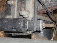
That first picture is all I need to see. That angle is way to shallow. Your spring moves vertical and the shock has to move almost horizontal. That is the dumbest idea I've ever seen. Who says engineers are smart. That will never work. You can purchase leaf spring plates (about $7) with holes drilled for the U bolts. They can be used as a shock mounting platform for a through bolt mounted shock. Last year I posted how to put shocks on our NT and I'm sure if you search my posts you can find it. After I post this I'll try and if I find the link I'll try to send it to you.

TeJay
 

GOTTOYS

Well-known member
It looks to me based on the misalignment of the upper shock mount vs: the shock itself, that the brackets were welded to frame in a position that would indicate the bottom of the shock would be placed ahead of the axle and it would be attached below the axle. This would put the shock in a more vertical position. If I decide to redesign this lash up I'm thinking that's the direction I will go. Shocks are supposed to move up and down to provide dampening, not to just flex on the rubber mounting grommets which does nothing..Don
 

TeJay

Well-known member
Ray,
I just noticed that the post count is staying the same on all of these posts per the individual. My post count is stuck at 240. Do they not update automatically?

TeJay

After I posted it jumped to 241
 

RoadJunkie

Well-known member
What is Lippert's position on this? Has anyone submitted a warranty claim, at least to have the bent shock replaced? Are they modifying the shock mount if a shock shaft is bent? Or, are they denying responsibility citing overloading?
 

Ray LeTourneau

Senior Member - Past Moderator
Ray,
I just noticed that the post count is staying the same on all of these posts per the individual. My post count is stuck at 240. Do they not update automatically?

TeJay

After I posted it jumped to 241
I think the way it works, every post you've ever mad changes to your total number of posts on the forum. The post date would be the best way to track them numerically.
 

TedS

Well-known member
Roadjunkie, yesterday I started the process with Lippert. First contact was with Customer Service and will follow up with submitting email with photos at their noncommittal suggestion. "Out of warranty" after just two years since purchase. I thought Lippert axle warranty was 2 years, not 1 year.
 

westxsrt10

Perfict Senior Member
TeJay

That slide side shock just dosn't have any room to mount it vertical because of the slide rotating bar. I mounted it as well as I could as shown in photo. (materials used, 3" muffler clamp, 2" angle iron)
 

Attachments

  • PICT0028.JPG
    PICT0028.JPG
    140.6 KB · Views: 82

TeJay

Well-known member
Westxrt10,
If you look at the travel of the axle as it hits bumps it will travel the same direction as the U-bolts, which is vertical. What you've done is a start but the axle movement is in a direction that is at odds with the shock movement. Shocks using the stud,rubber grommet and washers does not have enough movement. That type of mounting is used when the axle travel and shock are very close to the same plane. Eye and bolt through is the best way of mounting in my opinion. Here's my suggestion on improvement. First of all your springs are mounted on the top of the axle. That just changes how things can be done. If you bought a spring plate which is the same plate that you currently have mounting the axle to the spring. They are available for about $6-8 at any axle place it will come with 4 holes drilled which will match the plate used on top where the U-bolts are bolted onto the axle. Take the U-bolts off and install the new plate on the bottom. Then install your top plate, U-bolts and torque. Now you have a plate on the bottom that can be used to mount the bottom of the shock in what every way you decide is easiest or fits your situation. I welded bolts on the plate and bolted the shock to the plate. The top of the shock would bolt through the top spring bracket which is already welded to the frame. Move the bolt onto the axle side which would make the shock more vertical.

I looked at your picture again and you could change to a bolt through shock and simply move the top of the shock more vertical and run the bold through the axle side of the upper welded bracket near the frame. If you don't change the bottom mounting bracket I think the mount that you have might twist or spin under stress. Using the Spring plate mounted with the U-bolts would not twist. Running those U-bolts through a new spring plate might require that the holes be drilled a little bigger to allow the arc of the U-bolt to seat a little better.

Please accept these as just suggestions. You've done some nice work and take my ideas as just that MY ideas. If what you did works that's great. I really enjoy doing stuff like this. My wife knows that I'm a "Putterer." I can't leave anything alone. I always have to try to improve what I have. It's just plane fun and net when the plan comes together and something works.

TeJay
 

57chevyconvt

Well-known member
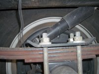
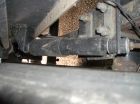
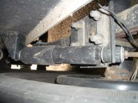
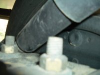
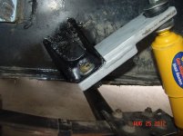
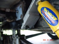
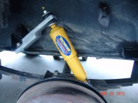
Just completed replacing 3 of the 4 wheel bearing with Japanese tapered roller bearing. I consider the Japanese bearing an upgrade over the OEM Chinese bearing. Since I had the wheels and hubs off, I decided to replace the shocks since two of the four shocking lower mounting bolts had broke off where they were bent due the angle of mounting. I replaced the shocks with Monroe no. 555001 RV shocks purchased from RockAuto.com. In order to elevate the angle of installation, I make a bolt on extension for the original Lippert backet locations as note in the pictures below.

DSC07229.jpgDSC07230.jpgDSC07228.jpg
 

Hastey

Oklahoma Chapter Leaders
Just completed replacing 3 of the 4 wheel bearing with Japanese tapered roller bearing. I consider the Japanese bearing an upgrade over the OEM Chinese bearing. Since I had the wheels and hubs off, I decided to replace the shocks since two of the four shocking lower mounting bolts had broke off where they were bent due the angle of mounting. I replaced the shocks with Monroe no. 555001 RV shocks purchased from RockAuto.com. In order to elevate the angle of installation, I make a bolt on extension for the original Lippert backet locations as note in the pictures below.


Jim,

That's a great mod. My trailer is new but I will be checking my bolts now. Can you post the specs to your extension? (length, width and approx angle changed to)

Personally I have been thinking that at their current angle that they don't do much good. JMHO
 

57chevyconvt

Well-known member
Rex,
I will do the best I can to explain how I arrived at the shock bracket details and will also attach a picture of a sketch that was make at the time of fabrication. The bracket changed the shock mount angle from 30 degrees to 60 degrees.
I thought about fabricating some of these brackets for sale to folks that have interest, but after I made the first bracket it became apparent that each of the brackets would be a little different due to the original Lippert shock mounting bracket on the trailer frame from one location to anther, i.e., the Lippert brackets are the same, it is just how the welder mounting the bracket that make the difference.
I used "3 X 1/2" flat bar stock because that was what was available, but 3" X 3/8" flat bar will work just as well. The two pieces that make up the bracket are 3" and 5" in length. I positioned the 3" X 3" piece up against the Lippert bracket and marked the location for the 7/16" dia. hole. I also drilled a 1/4" dia. hole ~ 1" from the center of the 7/16" hole to be used for a 1/4" roll pin. After bolting the 3 X 3 piece to the Lippert shock bracket, I then placed the 3" X 5" piece up against the shock bracket and the frame beam, then clamped the two pieces together for removal and welding. I drilled a 5/8" dia. hole in the new bracket to accommodate the 3/8" stud on the end of the shock. The reason for the larger hole is to allow some movement of the shock stud bolt without putting the shock in a bind such as what is being done with the original installation. Back to the roll pin, the purpose of the roll pin is to prevent the new bracket from rotating on the Lippert mounting bracket. There in not enough room for a second bolt of any size on the bottom plate of the new bracket. Because of the design of the new bracket, I doubt if the bracket would move due to the way the new bracket fits up against the Lippert bracket. If you decide to fabricate some brackets such as I have done, I would recommend using a grade 5 or better 7/16" bolt (cap screw) for mounting the new bracket. I also used some Loctite to keep the nut from coming loose. If you have any more questions, you can send me a PM and we will exchange phone numbers. SKETCH PICTURE below.
 

Attachments

  • Sketch - Bracket 1.jpg
    Sketch - Bracket 1.jpg
    108.1 KB · Views: 36
  • Sketch - Bracket.jpg
    Sketch - Bracket.jpg
    96.1 KB · Views: 33
Last edited:

Hastey

Oklahoma Chapter Leaders
Thanks, Jim!

What I seen in your pics I don't think that the roll pins are not necessary either. I will be tearing down and redoing bearings in the near future and will do this mod. Thanks for the info and the prints especially the info that not everyone is the same. I would have spent an hour or so with and adult beverage mass producing just to wind up with an oh crap moment later:cool:
 
Top