AC Current Requirements for Ceiling Fan and Fireplace

Hi. This is my first post to a forum, but I've learned a lot reading through many of the forums. I am trying to determine which circuits to power through an inverter. I plan to move the circuits to a subpanel. I know for sure that I will power the GFCI, bedroom, and living room outlets and the microwave with the inverter. I am trying to find out the current requirements for the ceiling fan and Greystone fireplace to decide whether to power these through the inverter. Thanks in advance for your help.
 

jimtoo

Moderator
Hi HarleyRider,

Welcome to the posting side of the Heartland Owners Forum and also to the family. If you have been lurking and looking around you have seen that we have a great bunch of people here and all willing to share their knowledge when needed.

If you don't have your owners manuals to check current listings, you might look in the "Tools" section to find your information. I''m sure the heater will be a 1500 watt unit, but the ceiling fan is probably not much. I'm sure some of our other members will be giving their opinions soon.

Enjoy the forum.

Jim M
 

brianharrison

Well-known member
I believe the fireplace is about 1700-1800W, (heater, fan, light combined). At 120V that would be about 15amps.
Most of the newer overhead fans draw little amperage, usually less than 1amp. The motors are 120-150W on high. Add the lights in (2x60W?), it may be near 2amps AC. Start up draw may be more.

Others may have additional information.

Brian
 

danemayer

Well-known member
You must have quite an array of batteries or solar panels if you plan on running the fireplace along with the other things listed. Might be more efficient to use the propane furnace. It uses a lot of battery power, but nowhere near what an electric fireplace would use.
 
Thanks Brian and Dan. I don't know if I would run the fireplace that much on the inverter but it would be nice to have that option, at least at 750 watts. Even if I don't turn on the heat it's nice to look at the 'simulated flame'. :cool: It's difficult to find any detailed info on these fireplaces but it would be nice to know the amperage draw without the heat on. I am guessing it not much. 2 amps for the fan is certainly doable.

Thanks Again, Scott
 

Jim.Allison

Well-known member
Screen Shot 2015-03-05 at 10.35.04 PM.jpg
Screen Shot 2015-03-05 at 10.34.25 PM.jpg


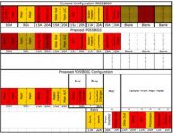
This is my sub panel

The fan is measured in watts, the energy to run it and the light, is about 180 watts. 120v * X = 180 watts = 1.5 AC amps. 1.5 ac amps = 15 DC amps + internal DC amps required to invert. OR less.

Your fireplace uses between 1000 to 2000 watts we will choose 1500 for this illustration.

1500/10=150 DC amps, plus the amps required to produce the AC electricity.
 

pegmikef

Well-known member
Thanks Brian and Dan. I don't know if I would run the fireplace that much on the inverter but it would be nice to have that option, at least at 750 watts. Even if I don't turn on the heat it's nice to look at the 'simulated flame'. :cool: It's difficult to find any detailed info on these fireplaces but it would be nice to know the amperage draw without the heat on. I am guessing it not much. 2 amps for the fan is certainly doable.

Thanks Again, Scott

The heater part of my fireplace is 750/1500 watts plus whatever the fan and the lights draw. There are three 40 watt bulbs and a small motor that rotates the flame simulator so I'd guess around 200 watts for just the light with no heat.
 
Thanks Jim. These old eyes aren't what they used to be. I would like to see what you put on the subpanel but I can't read most of the words in the graphic. Any chance you have a clearer picture or could you list the circuits? Scott
 

brianharrison

Well-known member
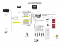
I added a subpanel to power the circuits that you have described in your earlier post: GFCI, bedroom plugs, kitchen plugs, and microwave. I have not added the fireplace, or overhead fan. I chose to use the 12V fantastic, MaxAirr fans in the overhead vents to move air while boondocking.

It looks something like this after it is done.

Link to my install thread, if it is of help in your planning.

Additional pics of the subpanel construction, if needed

Hope this helps,
Brian
 

Attachments

  • Voltage_Electrical_After.jpg
    Voltage_Electrical_After.jpg
    180.1 KB · Views: 34

Jim.Allison

Well-known member
I cant read it either, trouble is that it is s screenshot. I will try to fix it and post it tonight. Send me an E-mail and I will send you the original page.
Thanks Jim. These old eyes aren't what they used to be. I would like to see what you put on the subpanel but I can't read most of the words in the graphic. Any chance you have a clearer picture or could you list the circuits? Scott
 
Thanks Brian your information has been very helpful. I see you installed your inverter with two 30A lines. What are the advantages of using two lines rather than one 30A line? I ask since the overall capacity of the inverter is 3000W / 110V = 27A.
 

brianharrison

Well-known member
Don't confuse the inverter capacity (3000W) vs the AC pass through. My inverter is wired for dual in/dual out AC, which means two hots (L1, and L2) with neutral and ground. It can pass through 30A on each leg for a total of 6000W AC. It has two automatic 30A transfer switches (one on each leg), and can support the total subpanel AC load on AC pass through, plus support the integral 150A DC Charger.

I used a 6/3 romex to wire from the main AC panel (dual ganged 30A breaker) to the inverter and from the inverter to the AC sub panel.

Hope this helps,
Brian
 

Jim.Allison

Well-known member
This is really the way to do it. I used only one pass through due to my lack of understanding at the time, in retrospect running both legs through would be best. I dont know what unit you have, but what I like is that the units with the pass throughs will balance the legs as needed, and assist startup loads with inverted power, especially in the case of running a generator, the inverter can provide the power while the generator winds up. I'm thinking about redoing my system so that I can use all these features instead of just half of them.

Don't confuse the inverter capacity (3000W) vs the AC pass through. My inverter is wired for dual in/dual out AC, which means two hots (L1, and L2) with neutral and ground. It can pass through 30A on each leg for a total of 6000W AC. It has two automatic 30A transfer switches (one on each leg), and can support the total subpanel AC load on AC pass through, plus support the integral 150A DC Charger.

I used a 6/3 romex to wire from the main AC panel (dual ganged 30A breaker) to the inverter and from the inverter to the AC sub panel.

Hope this helps,
Brian
 

Jim.Allison

Well-known member
Screen Shot 2015-03-06 at 9.57.21 PM.jpg
Screen Shot 2015-03-06 at 9.57.41 PM.jpg
Screen Shot 2015-03-06 at 9.57.59 PM.jpg
Screen Shot 2015-03-06 at 9.58.19 PM.jpg

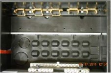
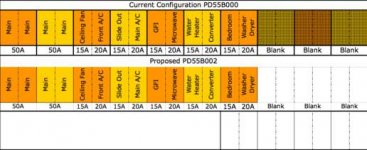
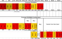
This progress breaker panel has a sub panel built in for one leg. In this case the leg is the pass through.

If you look on the (lack of a better word) tangs, every other one is assigned to L2 or L2. The Xantrex is an "appliance assigned to a 30 amp breaker. The L1 and L2 are theoretically balance, the appliances that get assigned to the pass through are protected by a 30 amp breaker and that "tang bar" carries all their breakers.

The very top photo is the original configuration, the other configs are with the new split panel note the difference in part number.

I tried to create a balanced system, and it must be, because I do not have any trouble with it. Even when I'm using a dog bone.

However after doing it this way, I decided that having both L! and L2 as inverter pass throughs would be a better set-up.
 

Attachments

  • Screen Shot 2015-03-06 at 9.40.22 PM.jpg
    Screen Shot 2015-03-06 at 9.40.22 PM.jpg
    19.6 KB · Views: 19
Top